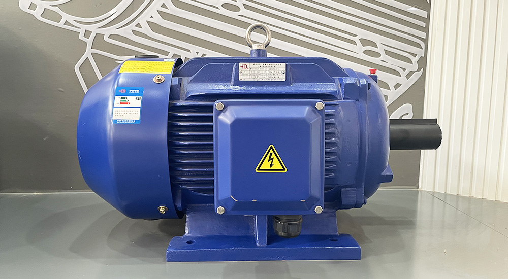
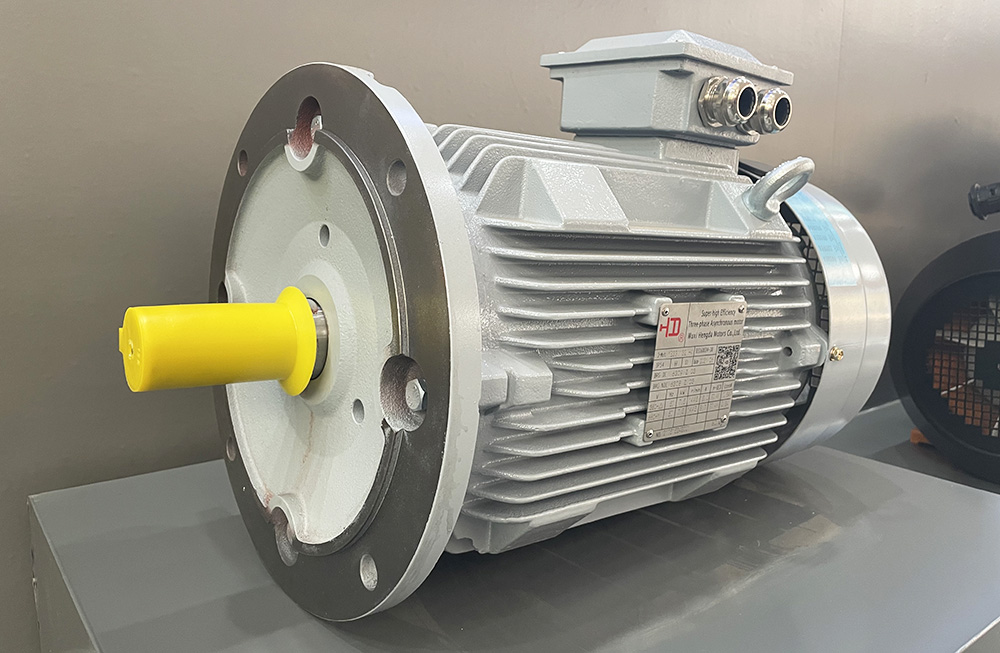
A three-phase motor is a device that can convert the AC power of a three-phase power source into mechanical energy. It usually consists of a rotor and a stator, which includes a fixed winding and an iron core, and is usually connected to a three-phase power supply. The rotor part is usually rotating and consists of a conductor and an iron core. Its movement converts electrical energy into mechanical energy, thereby realizing its operation.
Three-phase motors have the following characteristics:
1. Featuring high power, high efficiency, and high reliability, it is widely used in the field of industrial automation.
2. It has stable rotational speed, strong load capacity, strong adaptability, and can adapt to various load situations.
"A three-phase power supply is required for normal operation, and its operating speed is proportional to the frequency of the power supply.".
According to the different winding types and rotor structures of different types of three-phase motors, there are different types of asynchronous motors, synchronous motors, DC motors, and so on.
In short, three-phase motors are widely used in industrial automation systems as equipment with simple operating principles, high efficiency, and strong reliability. They are an indispensable and important component in modern industrial production.
Operating principle of three-phase motor
A three-phase motor is a device that converts electrical energy into mechanical energy, and its working principle mainly includes the following aspects:
1. Three-phase power supply connection: Connect the three-phase power supply to the three windings of the motor to generate a rotating magnetic field.
2. Generation of rotating magnetic field: The current circulates through the three windings of the motor, generating a rotating magnetic field.
3. Magnetic field effect: The size and direction of the rotating magnetic field continuously change, exerting an effect on the stator of the motor, thereby generating a rotating force that drives the rotor to rotate.
4. Rotor generates induced electromotive force: When the rotor starts to rotate, it will cut the magnetic field and generate induced electromotive force due to its movement in the rotating magnetic field.
Induced electromotive force generates current: The induced electromotive force will generate a certain amount of current in the conductor of the rotor.
6. Current action: The current will generate a magnetic field in the rotor and cannot change sharply. In order to match the rotating magnetic field, it must follow the rotating magnetic field to rotate.
7. Rotation speed: During motor operation, the rotor and rotating magnetic field move together, but due to a certain load, the rotation speed of the rotor will be slightly lower than the speed of the rotating magnetic field. This difference is called slip.
Through the above steps, three-phase motors can convert electrical energy into mechanical energy, driving the operation of various equipment and machinery. It should be noted that three-phase motors require additional power or special control circuits to control the current during startup to ensure the generation of rotating magnetic fields and the rotation of the rotor.

Operating principle of positive and reverse rotation of three-phase motor
The forward and reverse rotation of a three-phase motor refers to the ability to change the direction of rotation of the motor. Its working principle is achieved by exchanging the wiring method of the power cable on the motor winding. Specifically, the working principle of three-phase motor forward and reverse rotation includes the following steps:
1. Change the wiring of the power cable: Change the connection method of the cable on the motor winding and introduce opposite rotation in the rotating magnetic field to change the rotation direction of the motor. This can usually be achieved through a toggle switch or an additional control circuit.
2. Magnetic field effect: During forward connection, the winding excitation generates a rotating magnetic field that acts on the stator of the motor, generating a rotating force that drives the rotor to rotate; When connected in the reverse direction, the direction of the rotating magnetic field of the motor is opposite, and the direction of the force is also opposite, thereby changing the direction of rotation of the motor.
3. Rotation speed adjustment: During the process of changing the rotation direction of the motor, it is also necessary to adjust the rotation speed as needed, which can be achieved by controlling the current.
Therefore, by changing the connection method of the power cable and changing the direction and magnitude of the magnetic field generated by the excitation of the motor winding, the rotation direction of the motor can be changed to achieve the purpose of positive and negative rotation. It should be noted that improper operation may lead to equipment damage and safety accidents, so it is necessary to strictly comply with safety operation specifications when performing forward and reverse rotation operations on the motor.
Wiring method for positive and reverse rotation of three-phase motor
There are two connection methods for positive and negative rotation of three-phase motors, namely, positive and negative rotation connection method and steering gear connection method.
1. Positive and inverse connection method
This method requires the use of a special three-phase motor forward and inverse wiring assembly, mainly including a forward and inverse switch and three power supply terminals. The connection method is as follows:
Connect the three-phase voltage to the positive and inverse switches;
Connect the head, middle, and tail power cords to the three power supply terminals according to the illustration;
Changing the position of the forward and reverse switches can achieve forward and reverse rotation.
This wiring method is simple to operate, but requires the preparation of special positive and inverse wiring components.
2. Steering gear wiring method
This method requires the use of a steering gear and an electric contactor, and the connection method is as follows:
Connect the three-phase voltage to the electric contactor in the order of head, middle, and tail;
Connect the three contacts of the electric contactor to the three wiring terminals of the steering gear;
Connect the forward and reverse control terminals of the steering gear to the power supply;
The output terminals of the steering gear are switched through reverse control of the electric contactor to achieve positive and negative rotation of the motor.
This wiring method is more complex, but it can fully utilize existing electrical components to achieve more flexible forward and reverse control.
It should be noted that no matter which wiring method is used, attention should be paid to electrical safety, ensuring correct wiring, and avoiding dangers such as short circuits. It is recommended to seek the assistance of professional technicians without understanding the motor wiring and control.

Wiring principle of positive and reverse rotation of three-phase motor
There are generally two methods for the forward and reverse transfer line principle of three-phase motors.
The first method is to use a relay control wiring method, which can achieve positive and negative rotation through the connection and switching of three relays. The connection method is as follows:
Connect the power supply to the three wires of the three-phase motor.
"The three wires are connected to the three relays (K1, K2, and K3), and connected to the normally closed contact (C), normally open contact (NO), and normally closed contact (C) of the relay.".
3. By controlling the relays, the connection and switching of the three relays are controlled to achieve positive and negative rotation of the three-phase motor.
The second method is to use an electric contactor and an adapter with switching function. The connection method is as follows:
Connect the power supply to the three wires of the three-phase motor.
The three wires are respectively connected to the electric contactor and connected to the three contacts of the contactor. Ensure that each contact is connected to a separate wire.
Connect the reverse output interface of the electric contactor to the forward output interface of the adapter, and connect the forward input interface to the power supply.
4. Switching the output of the adapter through reverse control of the electric contactor can achieve positive and negative rotation of the three-phase motor without cutting off the power supply.
In short, no matter which method is used, it is necessary to connect and control according to the corresponding wiring principles to achieve the positive and negative rotation of the three-phase motor. If you are unfamiliar with motor wiring and control circuits, it is recommended to seek guidance from professional technicians.
How to Look at Forward and Reverse Rotation of Three-phase Motors
Viewing the positive and negative rotation of a three-phase motor requires distinguishing between two situations:
1. Under no-load operation without load
When there is no load, the forward and reverse rotation of the motor can be easily observed and detected. First, after turning on the three-phase power supply, observe the direction of rotation of the motor. If the motor rotates clockwise, it indicates positive rotation; If the motor rotates counterclockwise, it indicates reverse rotation.
2. Under load and working load
In the case of a load, due to the impact of external loads, the actual operation of the motor may be reversed from the power supply, requiring detection by other means. Here are the specific methods:
Method 1: Detection by rotating tools
You can take a piece of paper or other sheet like tool and place it closer to the direction of rotation of the motor (the direction of the extension line of the motor axis) to make it move due to the rotation of the motor. If a piece of paper or other tool moves forward, it indicates that the motor is rotating forward; If it moves rearward, it indicates that the motor is reversing.
Method 2: Detection by measuring current
The operating direction of a squirrel cage three-phase asynchronous motor is detected by the current changes in the three coils. When the motor is rotating forward, the phase sequence of current changes is A → B → C; When the motor reverses, the phase sequence of current changes is C → B → A.
In general, whether with or without load, the operating direction of a three-phase motor can be determined by observing the direction of rotation of the motor, or by measuring it with a detection tool. It should be noted that in order to ensure the normal operation of the motor, regardless of the method used for testing, it is necessary to strictly follow the relevant safety regulations for the use of the motor.


